ESP32 Cảm Biến Màu TCS3200D/TCS230
Hướng dẫn này sẽ giúp bạn kết nối cảm biến màu TCS3200D/TCS230 với ESP32 để phát hiện và đo màu RGB một cách chính xác. Học cách hiệu chuẩn cảm biến và lập trình ESP32 để đọc giá trị màu từ các vật thể.
Những gì bạn sẽ học được:
- Kết nối cảm biến màu TCS3200D/TCS230 với ESP32
- Hiệu chuẩn cảm biến để bù trừ các yếu tố môi trường
- Viết code ESP32 để đo và xuất giá trị RGB
Phần Cứng Cần Thiết
| 1 | × | 38-pin ESP32 ESP-WROOM-32 Dev Module - Narrow | Amazon | |
| 1 | × | Alternatively, 38-pin ESP32 ESP-WROOM-32 Dev Module - Wide | Amazon | |
| 1 | × | Alternatively, 30-pin ESP32 ESP-WROOM-32 Dev Module - Wide | Amazon | |
| 1 | × | Alternatively, ESP32 Uno-form board | Amazon | |
| 1 | × | Alternatively, ESP32 S3 Uno-form board | Amazon | |
| 1 | × | Cáp USB Type-C | Amazon | |
| 1 | × | Module Cảm Biến Nhận Dạng Màu TCS3200D/TCS230 | Amazon | |
| 1 | × | breadboard (Bo mạch thí nghiệm) | Amazon | |
| 1 | × | Dây Jumper | Amazon | |
| 1 | × | (Khuyến nghị) Screw Terminal Expansion Board for ESP32 | Amazon | |
| 1 | × | (Khuyến nghị) Breakout Expansion Board for ESP32 | Amazon | |
| 1 | × | (Khuyến nghị) Power Splitter for ESP32 | Amazon |
Or you can buy the following kits:
| 1 | × | DIYables ESP32 Starter Kit (ESP32 included) | Amazon | |
| 1 | × | DIYables Sensor Kit (18 sensors/displays) | Amazon |
Về Cảm Biến Màu TCS3200D/TCS230
TCS3200D/TCS230 sử dụng ma trận 64 photodiode được sắp xếp theo cấu hình 8×8 để nhận dạng màu sắc. Ma trận này bao gồm 16 photodiode được trang bị bộ lọc quang học màu đỏ, 16 với bộ lọc xanh lá cây, 16 với bộ lọc xanh dương, và 16 không có bộ lọc (trong suốt). Cảm biến hoạt động bằng cách chọn các loại bộ lọc cụ thể và chuyển đổi cường độ ánh sáng phát hiện được thành tín hiệu đầu ra sóng vuông điều chế tần số.
Hầu hết các module cảm biến đều có hệ thống chiếu sáng LED trắng tích hợp, giúp duy trì tính nhất quán của phép đo bằng cách cung cấp nguồn sáng được kiểm soát độc lập với điều kiện ánh sáng xung quanh.
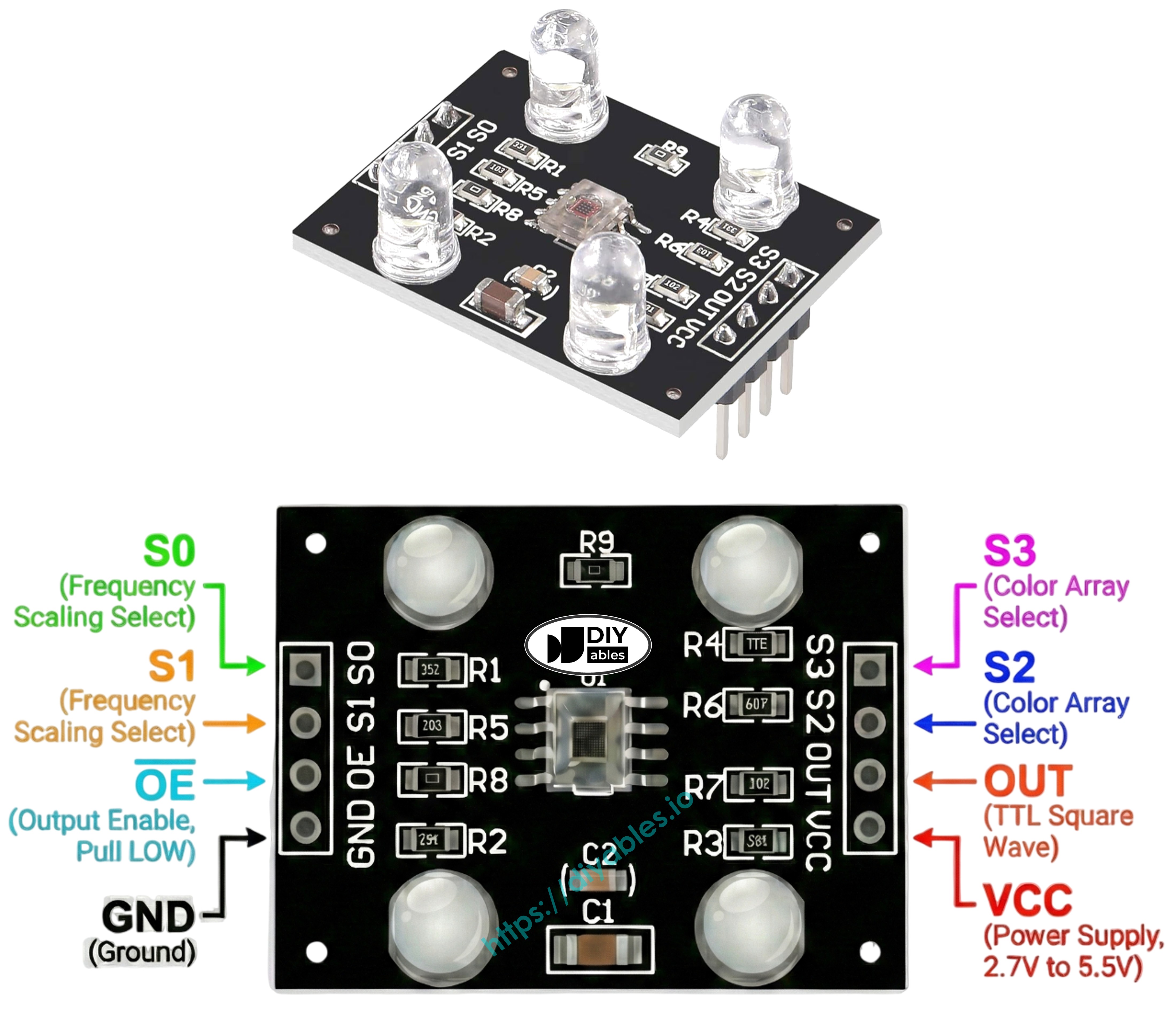
Sơ Đồ Chân
Module cảm biến TCS3200D/TCS230 cung cấp các điểm kết nối sau:
- Chân VCC: Kết nối với nguồn cung cấp 3.3V hoặc 5V.
- Chân GND: Kết nối với mass (0V).
- Chân S0, S1: Điều khiển tỉ lệ tần số đầu ra.
- Chân S2, S3: Bộ chọn bộ lọc màu.
- Chân OUT: Tín hiệu đầu ra tần số sóng vuông.
- Chân OE: Kích hoạt đầu ra (active LOW). Thường được nối sẵn với GND trên các module thương mại. Nếu có tiếp cận được, hãy nối với GND.
Cách Hoạt Động
Hoạt động của cảm biến phụ thuộc vào hai tham số có thể cấu hình: bộ lọc màu hoạt động và cường độ tín hiệu đầu ra. Hai cặp chân điều khiển xác định các cài đặt này:
Chân S0/S1 cấu hình tỉ lệ tần số đầu ra:
- S0=LOW, S1=LOW: Cảm biến tắt nguồn
- S0=LOW, S1=HIGH: Đầu ra ở 2% tần số cơ bản
- S0=HIGH, S1=LOW: Đầu ra ở 20% tần số cơ bản
- S0=HIGH, S1=HIGH: Đầu ra ở 100% tần số cơ bản
Chân S2/S3 chọn bộ lọc màu hoạt động:
- S2=LOW, S3=LOW: Kích hoạt bộ lọc đỏ
- S2=LOW, S3=HIGH: Kích hoạt bộ lọc xanh dương
- S2=HIGH, S3=LOW: Không có bộ lọc (trong suốt/không lọc)
- S2=HIGH, S3=HIGH: Kích hoạt bộ lọc xanh lá cây
Chân OUT tạo ra tần số đầu ra từ khoảng 2 Hz đến 500 kHz. Độ lớn tần số tương quan với cường độ ánh sáng—nhiều ánh sáng hơn cho tần số cao hơn. Sử dụng pulseIn() để đo độ rộng xung cho kết quả ngược lại—độ rộng xung thấp hơn cho thấy ánh sáng sáng hơn. Sau khi hiệu chuẩn, các phép đo này chuyển đổi thành giá trị RGB tiêu chuẩn 0-255.
Tối Ưu Hóa Độ Ổn Định Đo Lường
- Đặt cảm biến cách bề mặt đích 1-3 cm với hướng nhất quán.
- Bật LED trắng tích hợp để có ánh sáng tiêu chuẩn hóa.
- Chặn các nguồn sáng bên ngoài để giảm biến đổi đo lường.
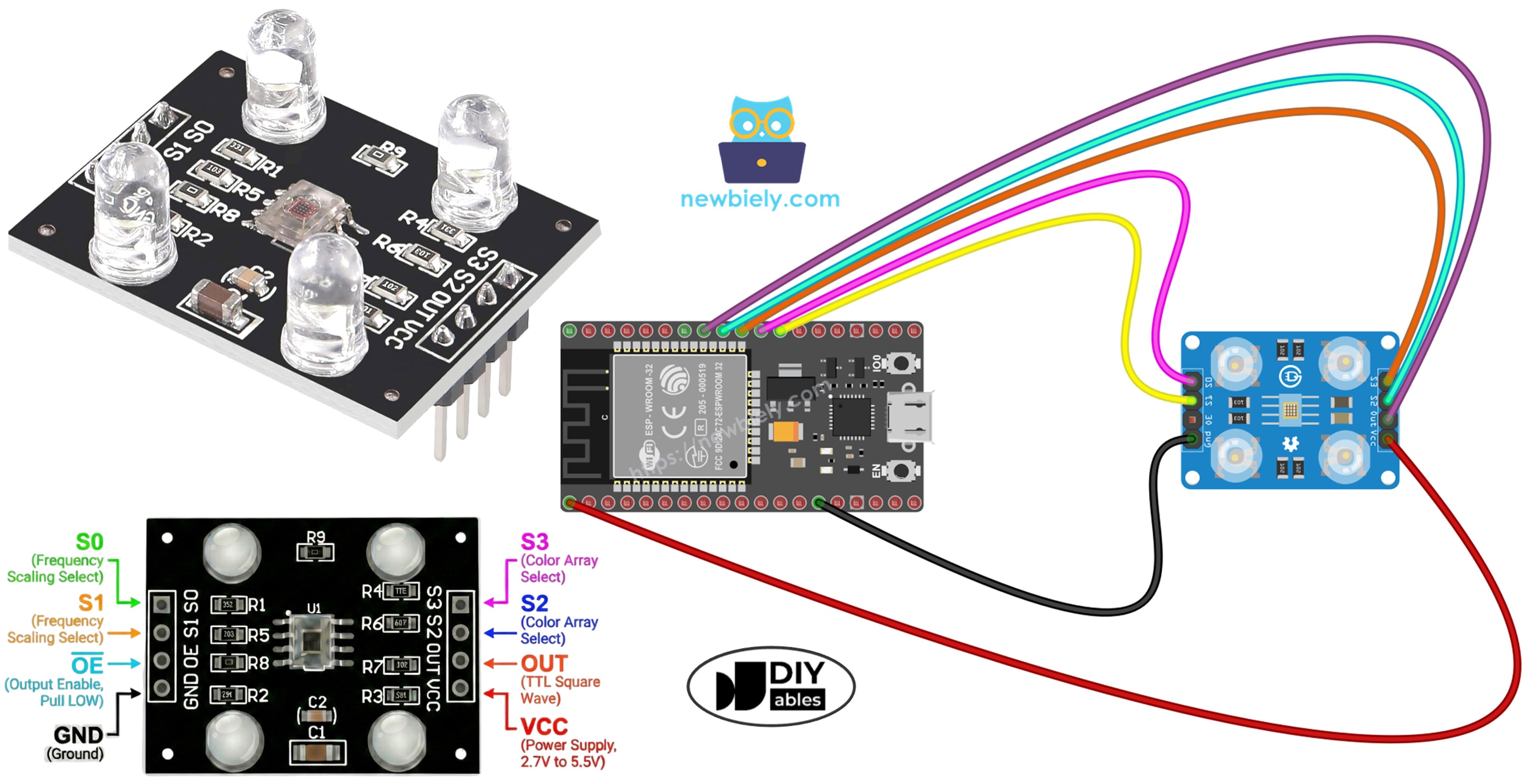
Sơ Đồ Đấu Nối
Sơ đồ kết nối ESP32 với cảm biến màu TCS3200:
| Cảm Biến Màu TCS3200 | ESP32 |
|---|---|
| VCC | 3.3V |
| GND | GND |
| S0 | GPIO 17 |
| S1 | GPIO 16 |
| S2 | GPIO 18 |
| S3 | GPIO 5 |
| OUT | GPIO 19 |
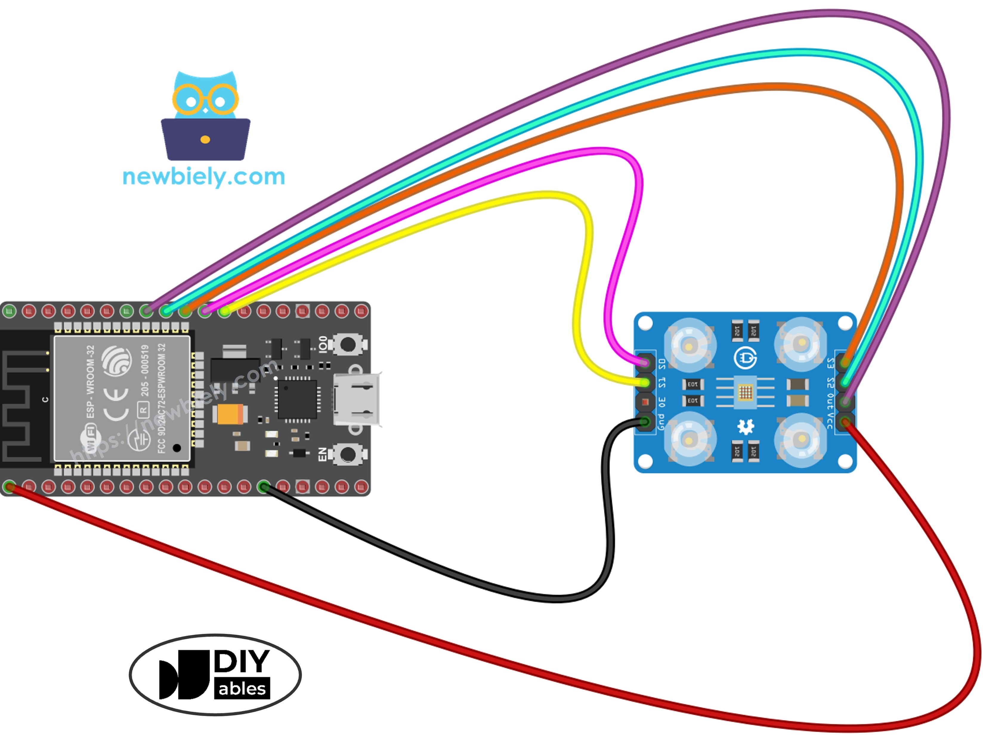
This image is created using Fritzing. Click to enlarge image
Nếu bạn chưa rõ cách cấp nguồn cho ESP32 và các linh kiện khác, xem: Cách Cung Cấp Nguồn Điện Cho ESP32.
Code ESP32 - Hiệu Chuẩn Cảm Biến Qua Độ Rộng Xung
Hiệu chuẩn bù trừ các biến số môi trường ảnh hưởng đến kết quả đọc thô của cảm biến: biến động độ sáng LED, khoảng cách vật thể, sự khác biệt về độ phản xạ bề mặt, và điều kiện ánh sáng xung quanh. Những yếu tố này tạo ra lỗi đo lường cần được định lượng. Quá trình hiệu chuẩn ghi lại độ rộng xung tối thiểu và tối đa cho mỗi kênh màu, tạo ra các ranh giới để ánh xạ RGB 0–255 chính xác trong môi trường cụ thể của bạn.
Các Bước Nhanh
- Nếu đây là lần đầu tiên bạn sử dụng ESP32, hãy xem ESP32 - Cài Đặt Phần Mềm.
- Sao chép code hiệu chuẩn vào Arduino IDE
- Nhấp vào nút Upload trên Arduino IDE để tải code lên ESP32
- Mở Serial Monitor (đặt baud rate là 9600)
- Hướng cảm biến về các vật thể có màu khác nhau: giấy trắng, bề mặt đen, và các màu khác nhau
- Theo dõi các giá trị Min/Max khi chúng tự động cập nhật
- Sau khi các giá trị ổn định (10-20 giây), ghi lại tất cả sáu số hiệu chuẩn
Kết quả hiệu chuẩn ví dụ từ đầu ra:
- RedMin = 42, redMax = 210
- GreenMin = 55, greenMax = 185
- BlueMin = 60, blueMax = 172
Code ESP32 - Đọc Giá Trị Màu RGB
Các Bước Nhanh
- Tìm các hằng số hiệu chuẩn ở đầu code:
- Thay thế tất cả sáu số 0 bằng các giá trị hiệu chuẩn thực tế của bạn. Ví dụ (sử dụng redMin = 42, redMax = 210, greenMin = 55, greenMax = 185, blueMin = 60, blueMax = 172):
- Sao chép code trên và mở bằng Arduino IDE
- Nhấp nút Upload trên Arduino IDE để tải code lên ESP32
- Đặt một vật thể có màu phía trước cảm biến
- Xem kết quả trên Serial Monitor
Đầu ra bây giờ hiển thị giá trị RGB tiêu chuẩn 0-255. Độ rộng xung ngắn hơn (ánh sáng sáng hơn) cho số RGB cao hơn; độ rộng xung dài hơn (điều kiện tối hơn) tạo ra giá trị thấp hơn.
Ý Tưởng Ứng Dụng Dự Án
Với khả năng đọc RGB hoạt động, hãy khám phá những khả năng dự án sau:
- Hệ thống phân loại màu tự động: Phân loại vật phẩm theo màu sắc (nhận dạng đỏ, xanh lá, xanh dương)
- Hệ thống so sánh màu: Xác minh sự phù hợp màu sắc giữa các vật thể
- Theo dõi đường màu: Xây dựng robot theo dõi các đường có màu
- Kiểm tra chất lượng sản xuất: Nhận dạng các đơn vị lỗi thông qua độ lệch màu
- Phản hồi kích hoạt màu: Kích hoạt buzzer hoặc chỉ báo khi phát hiện màu cụ thể
Video Tutorial
Việc sản xuất video tốn rất nhiều thời gian. Nếu video hướng dẫn hữu ích cho việc học của bạn, hãy đăng ký kênh YouTube để ủng hộ. Nếu nhu cầu đủ cao, chúng tôi sẽ cố gắng làm thêm nhiều video.
Tham Khảo Hàm
Bài hướng dẫn liên quan
📱 Ứng dụng đề xuất
 English for KidsHọc tiếng Anh vui nhộn cho trẻ nhỏ.Tải về trênGoogle PlayTải về trênApp Store
 Bubble NoteGhi chú tự xóa — viết như nhắn tin.Tải về trênGoogle PlayTải về trênApp Store
 Tôi Không MuaĐánh bại mua sắm bốc đồng, tiết kiệm hơn.Tải về trênGoogle PlayTải về trênApp Store
 Con Đường Tri ThứcBài thi thử để học mọi thứ.Tải về trênGoogle PlayTải về trênApp Store